Hardware setup
Match the board before you flash.
These six setup guides cover selected Cyber Controller profile paths. Confirm the exact board variant, firmware choice, and writable target before you start.
Firmware downloads need internet unless compatible images are already available on your machine.
Before you start
Three checks before you flash.
- 01
Match the target. Check the model, chip, display, USB layout, and storage device against the selected profile.
- 02
Protect your data. Back up anything important. Firmware writes and removable-media images overwrite the selected target. Choosing the wrong target can permanently destroy unrelated data.
- 03
Operate lawfully. Use device and radio features only with hardware and networks you own or are explicitly authorized to test. Do not interfere with other systems or networks.
ESP32 display path
CYD + ESP32 Marauder
Match the exact Cheap Yellow Display variant before selecting a Marauder image set.
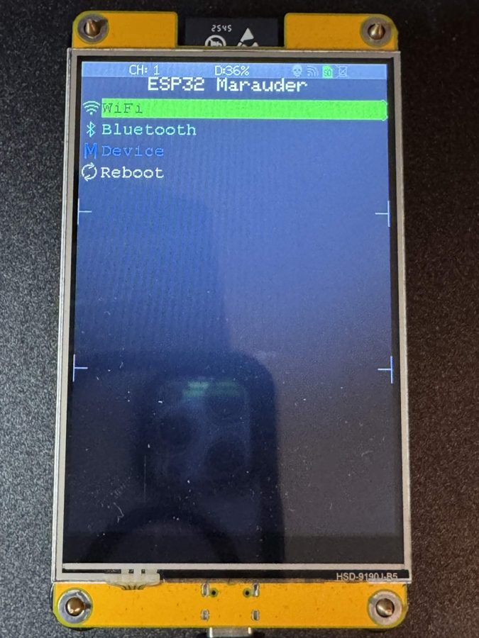
What you need
- A CYD variant listed for the selected Marauder profile. Current choices include 2.4-inch Guition, 2.8-inch, 2.8-inch 2-USB, and 3.5-inch targets.
- A USB cable that carries data.
- Internet access unless the required firmware files are already available locally.
Flash sequence
- Read the board marking and note the screen size and USB layout.
- Connect the board with a data cable. If no port appears, identify the board's USB bridge and install its driver.
- Choose ESP32 Marauder, then select the variant that matches the board rather than choosing by screen size alone.
- Start the flash. Cyber Controller resolves the support files and app image for the selected variant. Leave the board connected until the flash finishes.
Removable-media path
Pwnagotchi
Write a Pwnagotchi image to removable media for a declared Raspberry Pi target.
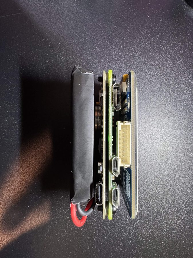
What you need
- A Raspberry Pi Zero 2 W or a supported Pi 3, 4, or 5 target listed by the selected profile.
- A removable microSD card large enough for the selected image.
- Administrator or root access for the raw disk write.
- Power for the Pi. A compatible display is optional.
Write sequence
- Insert the microSD card and confirm that the operating system detects it as removable media.
- Select Pwnagotchi and the image intended for your Pi model.
- Choose the detected removable target, then recheck its name and capacity before confirming. The write overwrites the entire selected removable drive; choosing the wrong drive can permanently destroy unrelated data.
- After the write completes, eject the card, install it in the Pi, and allow extra time for the first boot.
LoRa path
Meshtastic node
Flash a supported LoRa board, then configure the radio region before use.
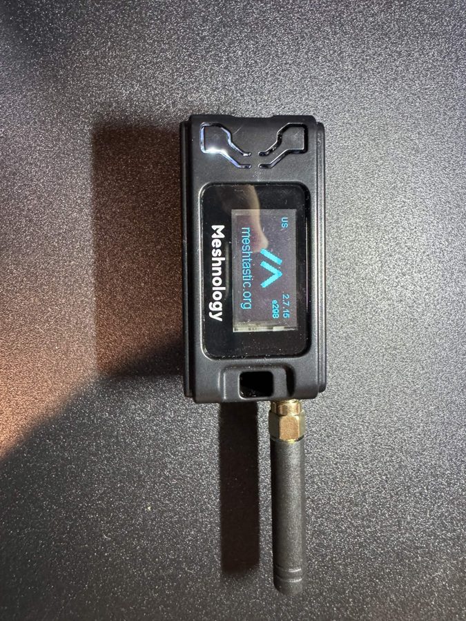
What you need
- A supported LoRa board listed for the selected Meshtastic profile.
- An antenna matched to the board and the frequency allocation for your region.
- A USB data cable.
Flash sequence
- Attach the correct antenna before powering or transmitting with the radio.
- Identify the exact board and regional band before choosing a firmware variant.
- Connect the board, choose Meshtastic, and select the matching target.
- Leave the node connected until the flash and restart finish. Configure the correct region in a Meshtastic client before radio use.
Realtek path
Dual-band BW16
Use Cyber Controller's separate AmebaD path for the Vampire Deauther profile on an RTL8720DN board.
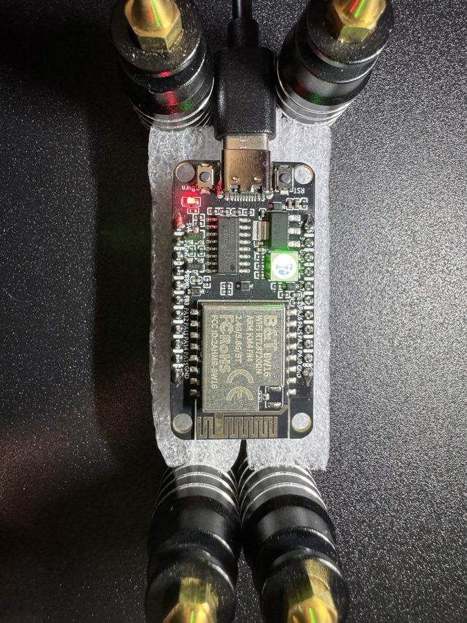
What you need
- A BW16 or RTL8720DN board supported by the selected profile.
- A carrier or USB-to-UART setup with the required DTR and RTS control lines.
- Realtek's
upload_image_toolinstalled on the host. It is required and is not bundled with Cyber Controller. - An RF-shielded or otherwise off-air test setup that prevents transmissions from reaching other networks.
- A USB data cable.
Flash sequence
- Prepare the supported carrier or UART wiring and verify the target port.
- Install or locate Realtek's upload tool before opening the flash path.
- Choose the BW16 profile. This path uses the AmebaD backend rather than the ESP32 esptool backend.
- Start the flash and leave the board connected until Cyber Controller reports the result.
ESP32 path
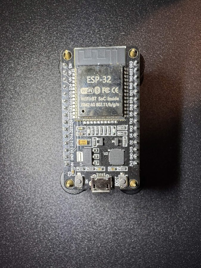
ESP32 dev board
Pair a listed board target with a compatible firmware variant.
What you need
- An ESP32 board explicitly listed for the selected profile and firmware variant.
- A USB data cable.
- The board's model, chip, flash capacity, and boot/reset controls identified before selection.
Flash sequence
- Identify the board rather than choosing from its shape alone.
- Choose a firmware profile, then select only a variant that names your board or documented equivalent.
- Connect with a data cable. If no port appears, identify the USB-serial bridge and install its driver.
- Start the flash. If automatic reset fails, follow the board's documented download-mode sequence.
ESP32-S3 path
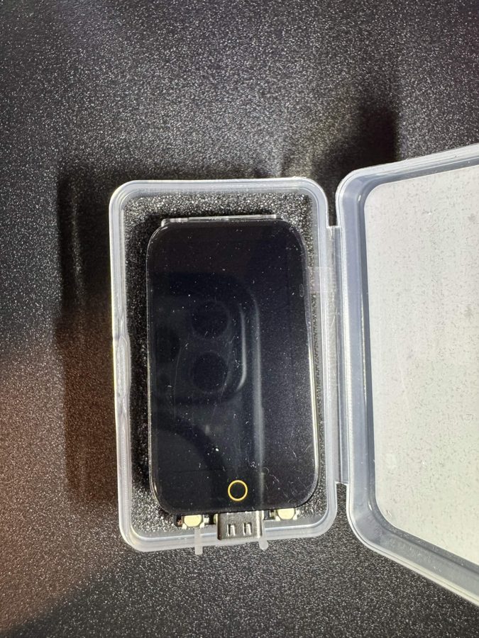
ESP32-S3 touch
Match the display, touch controller, flash layout, and USB path to the selected target.
What you need
- An ESP32-S3 touch board listed for the selected profile.
- A firmware variant matching the display and touch hardware.
- The board's intended USB port and a data-capable cable.
Flash sequence
- Record the exact model, display resolution, touch controller, and USB port.
- Choose the firmware and board variant that matches those details.
- Connect and select the expected port. Some S3 boards route native USB; others use a separate bridge.
- If the port does not appear, follow the board vendor's download-mode instructions. Use BOOT and RESET only when that board documents the sequence.
- Start the flash and wait for the final result before disconnecting.